
The Big Shader Graph Tutorial: Introduction
Edit: This article is a part of our shder graph tutorial series. If you would like to see the full list of the tutorials, you can click here.
This is the first part of a fundamental tutorial about
What is the Shader Graph?
One of the most important parts of a game engine is the shader system. There are different graphics programming APIs like OpenGL, DirectX, Metal or Vulkan. These APIs are used to communicate with the GPU. When you want to render something on the screen, you have to use one of these APIs which are also dependent on operating systems. This is a problem for a game engine that can export a project to different platforms.
Unity shader system uses Cg shading language (very similar to Microsoft’s HLSL language) and behind the shader, it compiles your shader code for different platforms. Therefore, there is no need to write the same code for different APIs.
Shader development is not an easy topic and you have to be familiar with
In order to simplify this work, Unity created surface shaders. This is not a new language but there are some simplifications via extra built-in functions and structs. Nevertheless, surface shaders still very complex for a hobbyist or a beginner game developer.
In recent years, Unity has been developing a new tool “shader graph” for developing shaders in a more intuitive way.
Shader Graph is a tool that you can create shaders visually. There are several built-in nodes which you can connect and create new shaders. If you want to learn shader development also, the shader graph may be a good starting point.
Preparation of Unity Project
As of Unity 2018, Unity announced the scriptable rendering pipeline(SRP). And also developed two new rendering pipelines in addition to the classic built-in pipeline. For more information on
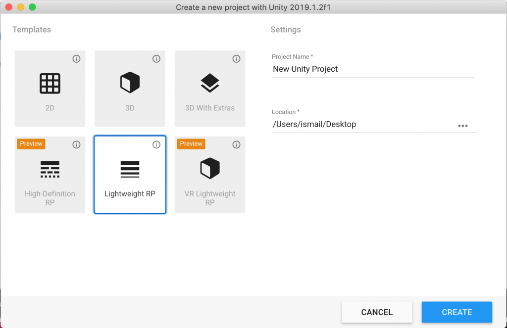
First of all, you should set up your project for LWRP. Open Unity Hub, create a new project and choose LWRP.
When the new project loaded, you will see a sample scene as well as several assets under the assets folder. You can remove them. I suggest you to create a new scene.
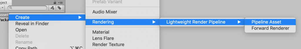
Then we have to create
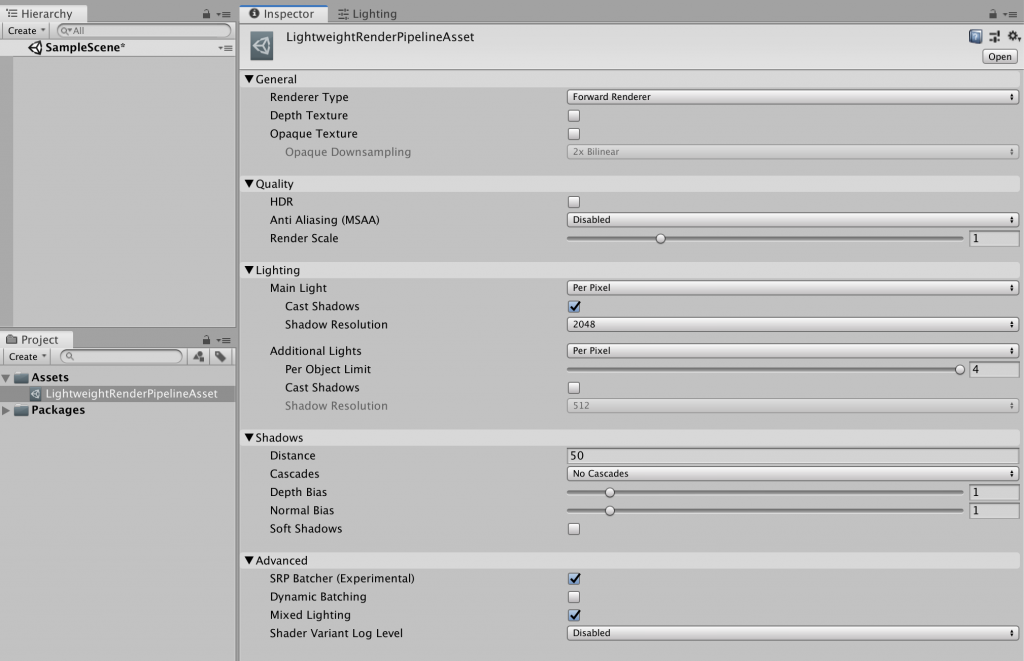
When you click the newly created pipeline asset, you will see the following in the inspector. You can change the rendering options here. For now, do not change anything.
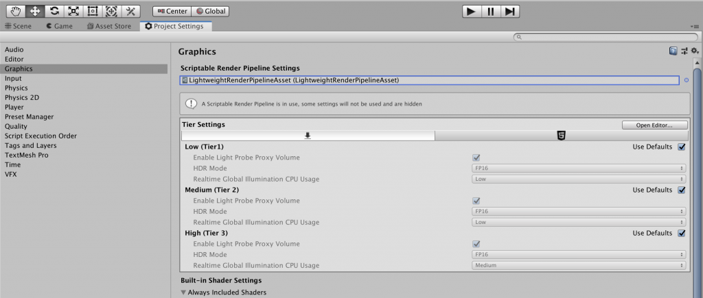
Now, we have to assign the new LWRP asset as the render pipeline that will be used. To do this, first open “Project Settings” from “Edit” at the top menu. From the left menu in Project Settings choose “Graphics”. Assign new LWRP asset to “Scriptable Render Pipeline Settings” as follows:
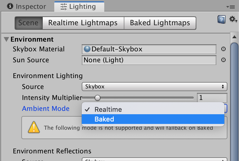
Finally, go to the
Everything is ready and now we can create our shaders using Shader Graph.
How do shaders work?
In this part of the tutorial, we will learn how shaders work. This will not be a deep explanation of it. We will only cover briefly most of the process. For a more technical point of view, you can read graphics rendering pipeline tutorial.
A 3D model is nothing but only a set of positions of the vertices in 3D space. When you export a model from a 3D model creation software like Maya, you actually export this set of mathematical coordinates. This data is called “vertex data”. Actually, there can be several other information of vertices in vertex data like vertex color, normal or tangent direction vectors but for now, just omit them and assume that vertex data only consists of vertex positions.
When the CPU wants to draw an object on the screen, it sends a set of instructions to the GPU. The name of this operation is “draw call”. A draw call is the start of the rendering pipeline. In GPU there are several stages that are executed consecutively which we will not cover here in detail. But let’s explain what is going on inside.
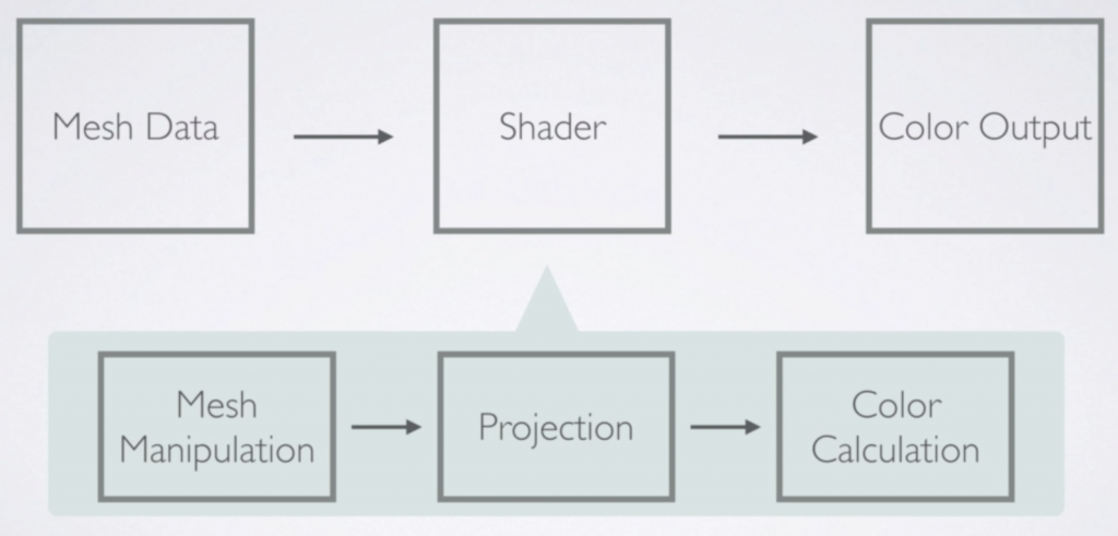
The first step inside the GPU is to project the vertex positions to the screen. Then GPU draws lines between vertices and determines if a pixel is inside the area or not. Finally, GPU makes the required calculations to determine the pixel color and returns this color.
The most important thing that you should know is all this process is a parallel operation. Shaders work for every vertex and pixel individually. Imagine that for each pixel, there is a factory behind. And this factory takes the vertex data and gives a color output for the pixel, independently.
Shader Graph is a tool that most of these process is hidden, therefore you do not have to deal with them mostly. This knowledge is sufficient for most of the time for shader development using Shader Graph.
Using Shader Graph you can manipulate vertex positions and pixel colors. This means that you can create authentic visual effects. And also you can achieve more photorealistic looking.
Creating First Shader
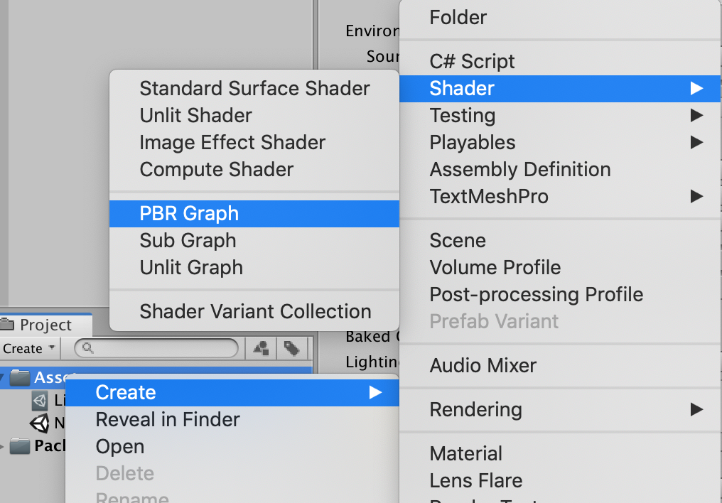
To create a shader using shader graph, right-click on the asset folder, then follow Create-Shader-PBR Graph.
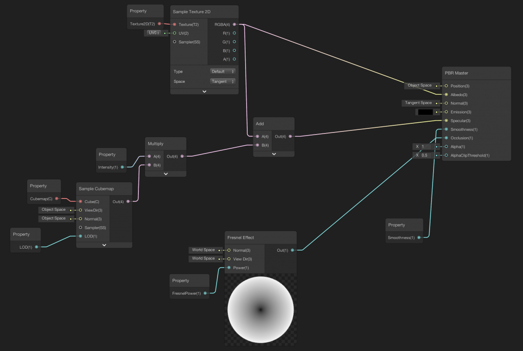
When you open the Shader Graph editor, you will see a PBR Master Node in the middle, and two windows on the top left and bottom right corners. The left one is the “Blackboard” and it will show the shader properties when we add, and the right one is the Main Preview. We will add nodes to the “playground” and connect them to the master node. We will see the changes in real-time in the Main Preview.
PBR Master Node
There are two different master nodes in the Shader Graph. These are the PBR master node and Unlit Master Node. Any other branch of nodes have to be connected to a master node. An Unlit Master Node is a node that there is no built-in lighting model in it. Therefore this master node is useful when you do not need lighting. Additionally, you can implement a custom lighting model using Unlit Master Node. Implementing a custom lighting model is not an easy topic and will not be covered here. In this tutorial, we are going to cover only PBR shaders.
PBR master node is a master node that you can create more photorealistic looking objects. PBR refers to “physically based rendering”. There is a built-in physically-based lighting model behind it. The shaders which you create will have a more realistic looking.
There are several input ports of a PBR master node. Let’s see them.
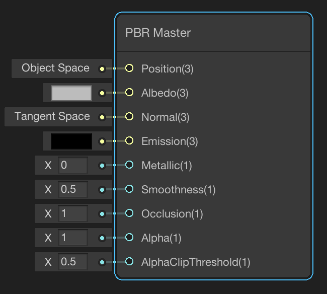
Position is a vector3 type input port which defines positions of vertex coordinates in object space. If we would like to manipulate vertex positions, then we have to use this port.
Albedo defines the color value of a point after texture mapping. If we would like to cover an object with a texture, this texture has to be mapped on the 3D mesh. Therefore for each point on the mesh, there will be a color value. This color value is in RGB colors and it is defined with a 3-dimensional vector.
Normal is the port for normal vector at a point. If you would like to use a normal map, then you have to map it to the 3D model and connect it to this port. If you do not use it, vertex normals will be used in lighting calculations. This is also in vector3 type.
Emission port is to define the emission color in RGB colors. If your object emits light, then you may use it. Otherwise, this will break photorealism.
Metallic port determines the metallic value of the object. This can be between 0 and 1. You can set a value for all points or you can map a metallic map to the object. This port is available for metallic workflow. You can change the workflow from the gear icon on the top right of the PBR master node.
Specular port is for specular reflection color. This is active only in the specular workflow. You can change the workflow from the gear icon on the top right of the PBR master node.
Smoothness port is the input for determining the smoothness of the surface at a point. If you map a smoothness map, then you can set different values for different points. Otherwise, this value is used for the whole surface.
Occlusion port is to define the occlusion value of the ambient.
Alpha input defines the alpha channel value. This is used for transparency.
Let’s Add Some Nodes!
As you can see from the PBR Master Node, there are predefined inputs to the ports. We can add new inputs from node branches. In addition to this, we can create shader properties and using these properties we can manipulate values from outside of the shader.
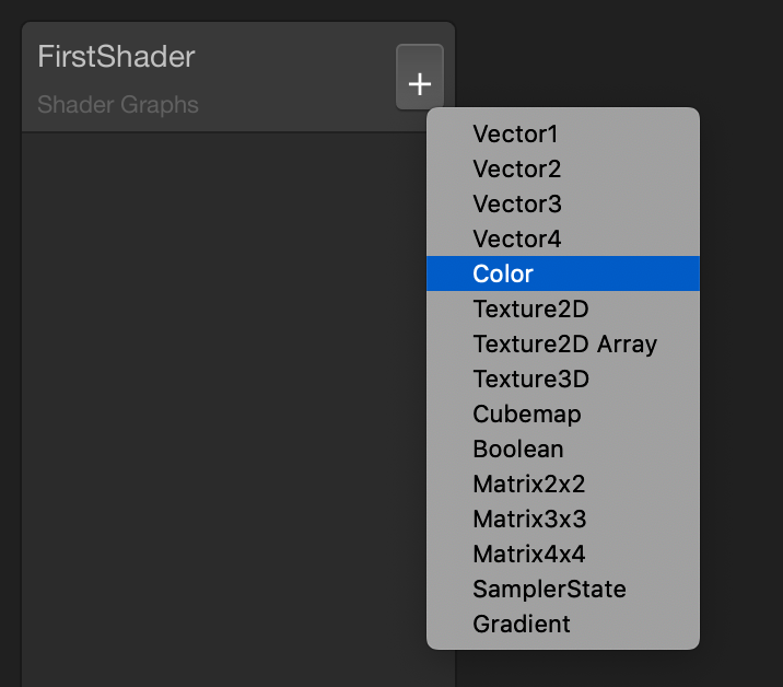
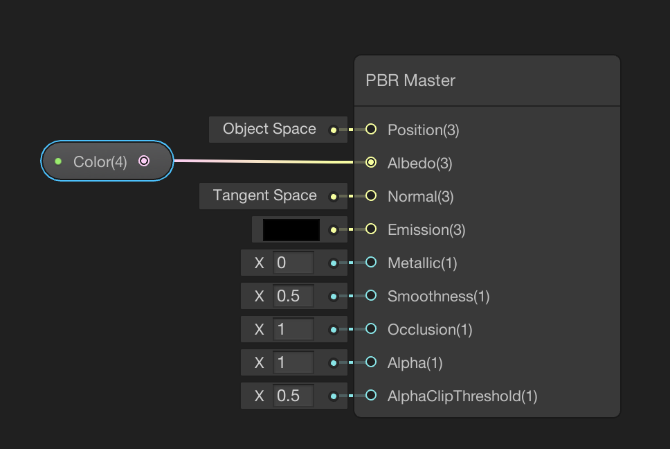
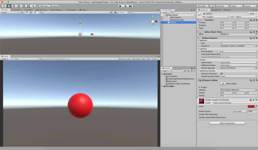
Let’s add a color property. To do this, click the plus icon on the Blackboard panel and choose Color. Drag and drop the Color property near PBR Master Node. Then connect it to the Albedo port. Save the shader and turn back to Unity Editor. Create a material for this shader and also create a 3D object. Assign the material to the object. From the material inspector, you can change the color of the object.
Actually, this shader does nothing fancy. It only changes the color of the object.
In this tutorial, we have learned a lot of things but have not created any fancy stuff yet. In the next part of the tutorial, we will create more fancy shaders.
References
https://docs.unity3d.com/Packages/com.unity.shadergraph@6.9/manual/index.html
https://www.udemy.com/course/introduction-to-shaders-in-unity3d-with-shader-graph/
Hello İsmail,
So nice to read everything and gaining more information. I really appreciate the time you spend to help other people learn.
I am currently working on my graduation project for my interaction design study: creating engaging biology lessons using Unity in WebGL. I will learn from this site, and use my knowledge to create learning experiences for students. 🙂 Everything is connected!
Thank you very much. It is nice to see they are helpful. 🙂