Coordinate Spaces and Transformations Between Them
In the previous article, we have created the first shader and also we explained its syntax and how it works. In this article, we will continue with the most important mathematics concept in shader development: Coordinate spaces and coordinate transformations.
Linear algebra and analytic geometry are languages of shaders. Shader development is mostly about transforming coordinates from one coordinate system to another coordinate system. I will try to explain details that are required here, but I also suggest you study linear algebra and analytic geometry if you want to master on shader development.
Contents
- Coordinate transformations
- Coordinate systems that are used shader development
- Inverse transformations
Coordinate Transformations
Suppose that you are driving a car on a road. You can determine the positions of the objects according to the car’s own coordinate system. For instance, the position of the rear-view mirror can be determined according to the local coordinate system of the car. But position of the same mirror is not the same for an observer who is sitting near the road. But how are these two coordinate systems related to each other? Can we obtain coordinates in one frame if we know the coordinates in another frame?
Assume that there are two different frames. There is always a transformation matrix that transforms positions from one frame to another frame. When we want to find the positions in the frame of reference, we multiply the transformation matrix and position vector in the first frame. For instance, in our example, if we know the position of the rear-view mirror that is relative to the origin of the car, and also if we have the transformation matrix between the car’s reference frame and observer’s reference frame, then we can find the position of the rear-view mirror in observer’s frame.
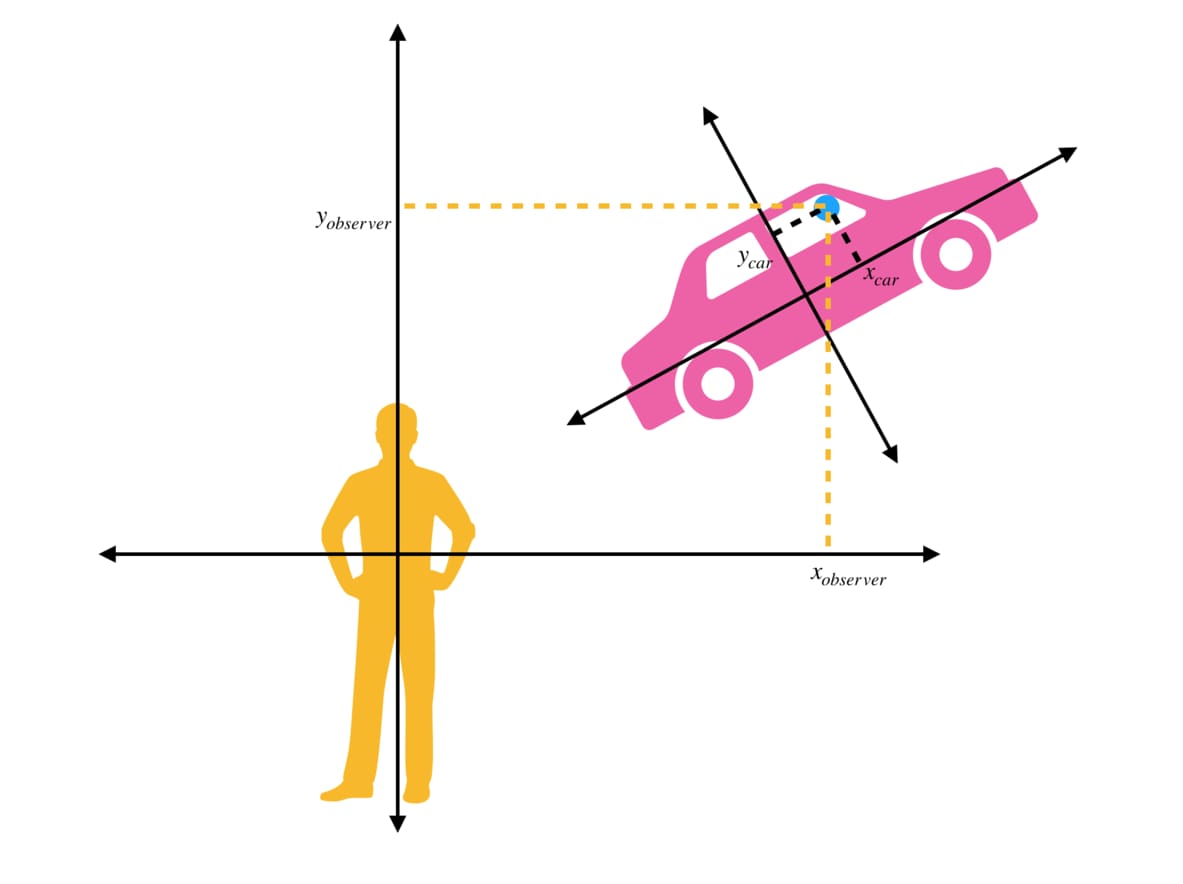
In the image above, while \( (x_{car}, y_{car}) \) represents the position of the rear-view mirror in the car’s own reference frame, \( (x_{oberver}, y_{oberver}) \) represents the position of the same mirror in observer’s reference frame.
If we know the transformation matrix T between car space and observer space, then we can calculate \( (x_{oberver}, y_{oberver}) \).
Even if this example is given in 2D coordinate spaces, they can be generalized to higher dimension coordinate spaces as well.
There is good news for Unity Developers. We do not have to construct transformation matrices for main coordinate spaces. There are pre-calculated built-in variables and built-in helper functions for these transformations.
In Cg, we use mul( ) function to multiply matrices.
transformedCoordinates=mul(transformationMatrix, coordinates);
Coordinate systems in shader development
Six of the most important coordinate systems in computer graphics are:
- Object Space
- World Space
- View Space
- Clip Space
- Screen Space
- UV Space
Object Space
This is the reference frame in which the vertex data is stored. This is a 3D coordinate space that uses the cartesian coordinate system. Its origin is the pivot point of the object.
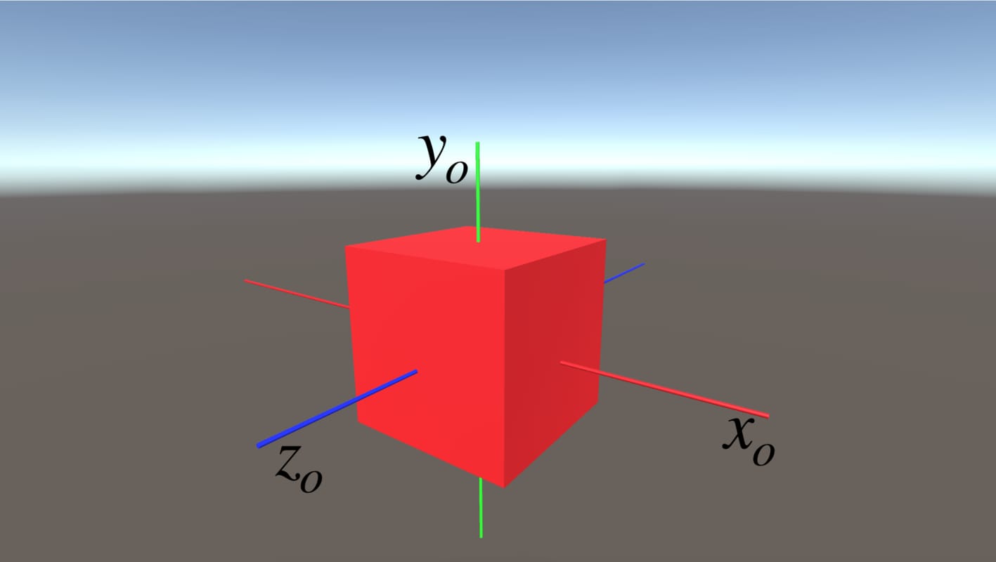
World Space
World space is the reference frame in which we make lighting calculations. We also use it when we manipulate something according to world space coordinates. It uses a 3D, cartesian coordinate system. The origin of the world space is the center of the scene.
If we want to obtain the coordinates of vertices of an object in world space, we need to transform object space coordinates to world space coordinates. The transformation matrix which transforms object space coordinates to world space coordinates is called “model matrix“. As we mentioned earlier, we do not have to construct it from scratch. The model matrix in Unity is given by unity_ObjectToWorld. Thus we can obtain world space coordinates by:
worldSpacePos=mul(unity_ObjectToWorld, objSpacePos);
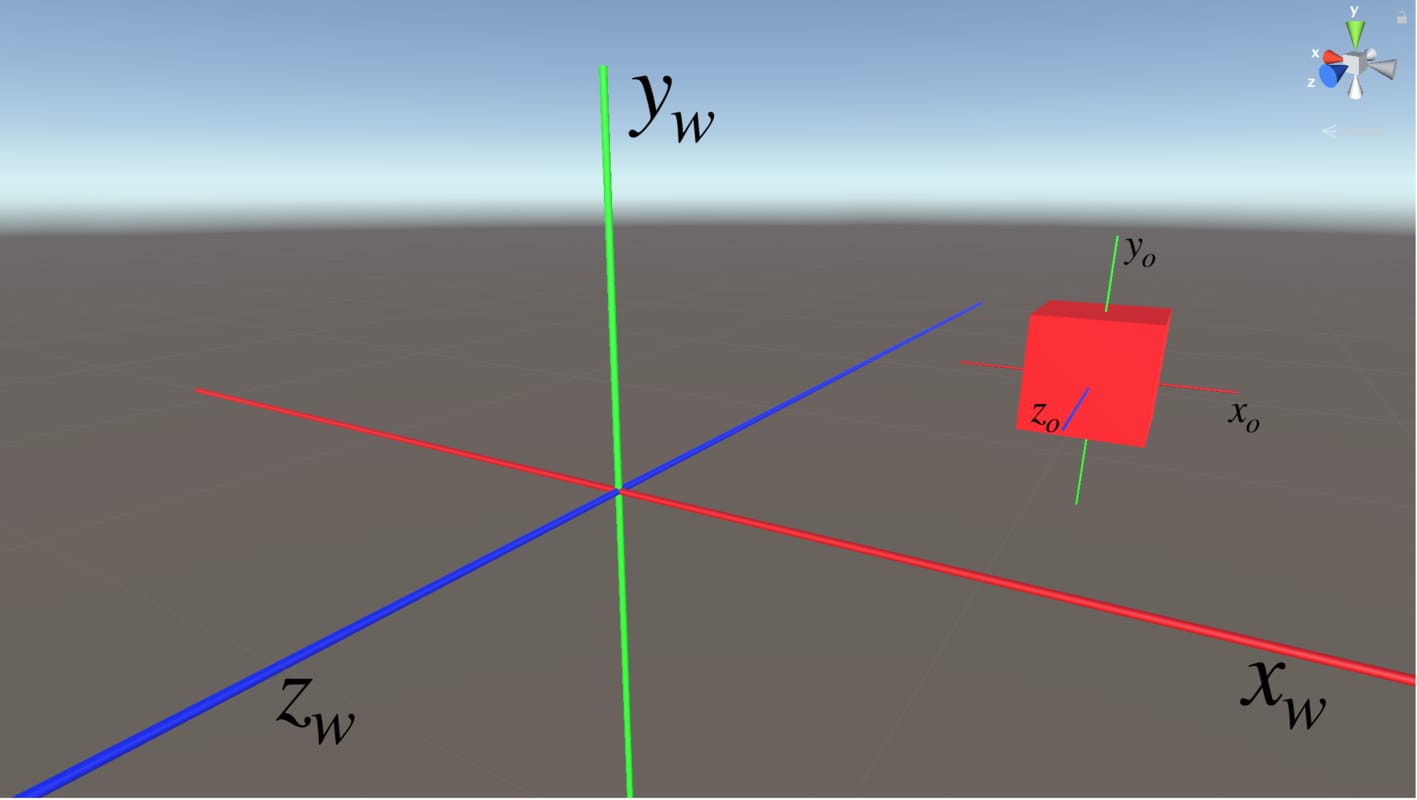
View Space
View space or camera space is a camera centered coordinate system. It is also a 3D coordinate space that uses the cartesian coordinate system. When we need to obtain coordinates of a point according to the camera, we transform the coordinates to the view space.
In order to transform coordinates from world space to view space, we use the “view matrix”. The view matrix in Unity is given by UNITY_MATRIX_V. We can obtain view space coordinates from world space coordinates as the following:
viewSpacePos=mul(UNITY_MATRIX_V, worldSpacePos);
Even though a transformation from the world space to the view space is used seldom, you should know how to do it.
A transformation from the object space to the view space is more common. The matrix for this transformation is the “model-view Matrix”. And it is given as UNITY_MATRIX_MV in Unity. To obtain the view space coordinates from the object space, we can use the following:
viewSpacePos=mul(UNITY_MATRIX_MV, objSpacePos);
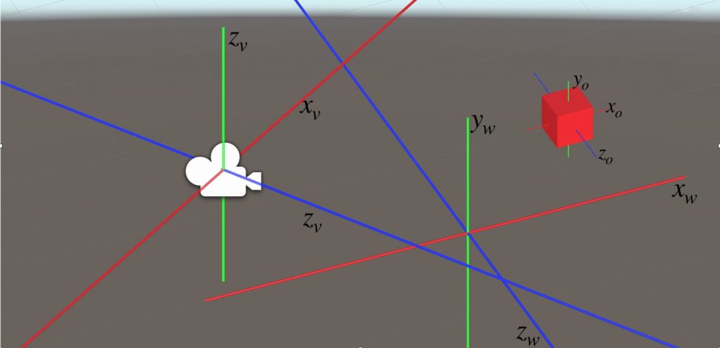
Clip Space
Clip space coordinates are the output of the vertex shader. This means that, at least, we have to transform local coordinates to clip space coordinates in vertex shader. There is a stage at the end of the vertex shader stage which is called clipping. Clipping determines which object or object parts will be rendered. For instance, an object which is out of the desired coordinates will not be rendered. This coordinate space is an interesting coordinate space that is a little bit confusing.
Even though the world is 3-dimensional, we represent clip space coordinates by 4 numbers. In clip space, we use a coordinate system which is called the “homogeneous coordinate system”. The reason for that is to create the illusion of perspective which we will discuss a little bit later.
The transformation matrix from view space to clip space is the “projection matrix“. The projection matrix is given by UNITY_MATRIX_P.
clipSpacePos=mul(UNITY_MATRIX_P, viewSpacePos);
This transformation is also used seldom. Generally, we use direct transformation from object space to clip space. We use the “model-view-projection matrix” to transform a coordinate from object space to clip space. In Unity, the model-view-projection matrix is given by UNITY_MATRIX_MVP.
clipSpacePos=mul(UNITY_MATRIX_MVP, objSpacePos);
Nevertheless, there is a built-in function that transforms object space coordinates to clip space coordinates. We generally use the following function to transform coordinates from object space to clip space:
clipSpacePos=UnityObjectToClipPos(objSpacePos);
Homogeneous Coordinate System
In Euclidean space, two parallel lines never intersect. On the other hand, as you are observed many times, train rails are seen as if they intersect at the infinity. To create this perspective, we use the homogeneous coordinate system in computer graphics.
Coordinates in the homogeneous coordinate system are represented by 4 numbers. The first three numbers represent the 3D coordinates and the fourth one is for creating perspective.
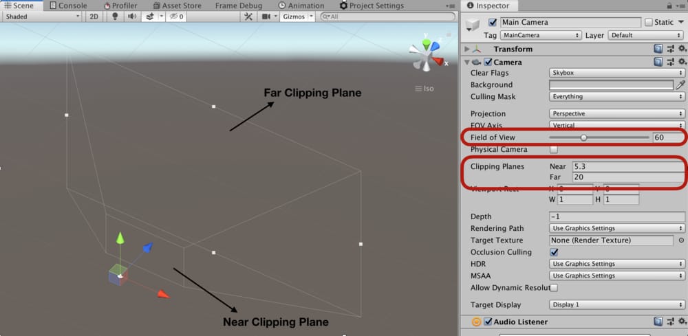
Clip space does not use rectangular coordinates. You can think of it as a truncated pyramid shape(also called a frustum). It consists of near clip plane, far clip plane, and field of angle. If you look to the camera a little bit closer you see these terms in the inspector.

Screen Space
Screen space is a 2-dimensional coordinate space in which a coordinate represents a pixel on the screen. We do not have direct control over it. In the rasterizer stage, clip space coordinates are automatically transformed to screen space coordinates.
UV Space
The UV space is a 2-dimensional coordinate space that is associated withobject. This space is used to cover the object with a 2D texture. Every coordinate on the object mapped to a point on the texture. This mapping uses UV space.
Inverse Transformations
Sometimes we need to make inverse transformations. For instance, when we want to transform a world space coordinate to object space coordinate, we have to multiply the inverse of the transformation matrix from object space to world space with the world space coordinates. In Unity, the inverse of the model matrix is given by unity_WorldToObject.
objSpaceCoordinates=mul(unity_WorldToObject, worldSpaceCoordinates);

